
Wb Menu


Frequency signal generator with adjustable pulse rate module PWM WS/20, Power 30mW
Working voltage: 3.3 ~ 30V, with protection against reverse during operation. Engine
Frequency range: 1Hz ~ 150KHz, accuracy approx. 1%

Safe shopping

Fast delivery

Hassle-free return of goods
24.166667 tax excl.
Frequency signal generator with adjustable pulse rate module PWM WS/20, Power 30mW
Working voltage: 3.3 ~ 30V, with protection against reverse during operation. Engine
Frequency range: 1Hz ~ 150KHz, accuracy approx. 1%
Operating cycle range: 0 - 100%, 1% rafting
Number of pulses: 1-9999 or infinite (display '----' means infinity)
Output delay time: 0.000 s - 9999 s, minimum can be set 1 ms
Positive and negative pulse width: 0.000 s - 9999 s, minimum can be set 1 ms
Signal carrying capacity: less than 30 mA
Output signal amplitude: amplitude equals supply voltage
Product size: 79 mm * 43 mm * 30 mm
Properties:
Drive for LED, engine, and other equipment.
It can be used to adjust the frequency and operating cycle, suitable for regulating LED brightness and engine speed.
Two modes can be selected: PWM: control frequency (continuous) and operating cycle. In this mode, the number of pulses cannot be adjusted and the pulse is looped on or off. PULSE: adjustable positive pulse width time, negative pulse width time, start time of power delay and number of pulses.
Use the Start and Stop buttons to control the output and stop the signal.
Widely used in industrial control of dc motor speed, speed control of industrial conveyor belt, lighting and lighting mediation, cooling of computer power supply, DC fans, etc.
Specifications:
Model: ZK-PP1K/20
Material: PVC and fiberboard
Size: approx. 79 x 43 x 30 mm / 3.11 x 1.69 x 1.18in
Working voltage: 3,3-30V
Frequency range: 1Hz-150KHz, accuracy is about 2%.
As a rule, engine speed control is elected at 20 KHz.
Operating cycle range: 0 - 100%, 1% rafting.
Number of pulses: 1-9999 or infinity (displaying '----' means infinity).
Output delay time: 0.000 s - 9999 s, minimum can be set 1 ms.
Positive and negative pulse width: 0,000 s - 9999 s, minimum can be set 1 ms.
Output load capacity: less than 8 A (MOS connecting tube).
Output amplitude: The amplitude is equal to the supply voltage (OUT + is directly connected to module V +).
Module description:
I Button operating instructions:
1. output of the MOS tube switch type, without wave form;
2. The number of open times reaches the set value, the output stops automatically and "out" disappears;
3. Press the On button to control the start and end of the output. OUT disappears to indicate no output, disabling output;
4. Reset the ON button to turn on the output, recalculation the number of open times;
II PWM mode (display has "%" for PWM mode)
1. The factory default mode is PWM mode, set frequency of FREQ + and FREQ keys, adjustment cycle of the BUTTONS DUTY + and DUTY; briefly press STOP
button control signal output or stop, stop output is 0, "OUT" is displayed on the screen if the output is, otherwise stops output; the default production frequency is 1KHZ and the operating cycle is 50%.
2. To switch to PULSE mode, long press the SET button (more than 6 seconds), do not release, you will see a change of screen, "%" will disappear, it is PULSE mode.
PULSE MODE III (No "%" on the right side of the display is PULSE mode)
1. The line above the LCD screen shows the time of the positive pulse width. The P+ and P- buttons set the parameter. The line below the LCD screen shows the time of the negative pulse width. The N+ and N- buttons set a parameter. Press STOP to control or stop the signal output.
When output is stopped, output is 0. On the screen appears "OUT" for output, otherwise stops output; the default positive pulse from the production width is 0.5 seconds and the negative pulse width is 0.5 seconds.
2. Setting the number of pulses and the delay time - In PULSE mode, press and hold the SET button for 2 seconds, and then release and enter the pulse number.
and the interface of the delay time setting, set appears on the screen, when turned off it turns off and clears. ; Use the P + and P- buttons to set the delay time, N+
and N-buttons set the number of pulses, the default delay time from production is 0 seconds, the number of pulses is infinite (the display ----); then press SET
button 2 Within seconds, it will automatically return to the impulse interface, press STOP, after the set delay time will start to issue the set
number of pulses. If the number of pulses is sent, it automatically issues zero. If the period is not sent, press STOP to turn it off.
The output pulse is switched off and erased and the set number of pulses is issued each time
IV Examples of how the application works
1. PWM 20KHZ output, 60% operating cycle: Select PWM mode, frequency is set to 20.00 and operating ratio is set to 060%.
2. The output is switched on for 0.6 seconds and switched off for 0.2 seconds. Infinite loop: select PULSE mode, positive pulse width is set to 0.600, negative pulse width is set to 0.200, delay time is set to 0.000, and pulse count is set to --- -.
3. Turn on or press the start button, delay 5 seconds, then the output turns on for 0.6 seconds, turns off 0.2 seconds, infinite loop: select PULSE mode, positive pulse width is set to 0.600, negative pulse width is set to 0.200, delay Time is set to 5,000 and the number of pulses is set to - -.
4. Turn on or press start button, delay 5 seconds, then output high level 10 ms low level 10 ms pulse 100: select pulse mode, positive pulse
the width is set to 0.010, the negative pulse width is set to 0.010, the delay time is set to 5,000, and the number of pulses is set to 0100.
5. Power-on delay for 10 seconds, then permanent output signal: select PULSE mode, positive pulse width is set to a number greater than 0,
the negative pulse width is set to 0, the delay time is set to 10.00 seconds, and the number of pulses is infinite. (----).
Count on an error of 0-1 cm for manual measurement. pls make sure you don't mind before you offer.
Specific References

The Long-Range Laser Listening Device (Laser Microphone) is a highly sophisticated surveillance apparatus that utilizes an invisible infrared laser beam to eavesdrop on a target.
This is the most effective long-range laser listening device in the world that allows the operator to conduct an undetectable surveillance operation on any targeted room with at least one window at an impressive distance of over 500 meters.
This laser microphone was specially developed for government and law enforcement organizations to use covertly in situations when entrance in buildings is not suitable or possible for placing a listening device into the targeted area. The Long-Range Laser Listening Device is also highly undetectable as the infrared laser is completely invisible to the naked eye.

quality hands-free phone for professionals.
The Gigaset S790 is a sleek wireless phone with advanced features. It is ideal for those who love the blueest technology, and those who have professional needs with professional sound quality. Excellent loud calls, up to 500 contacts and a list of the last 20 missed calls

The device also contains 4 relays that respond to the settings of min and max values. Power supply AC230V via mains. IN adapter. Automatic digital display Liquid level indicator in the tank - water level regulator.

3.3V output: 4.5-30V input, 3.3V output (± 3%)
5V output: 6.5-30V input, 5V output (± 3%)
12V output: 13.5-30V input, 12V output (± 3%)
AJD output: 4.5-30V input, adjustable 2-28V output
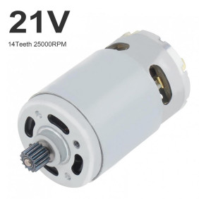
Motor for 18V - 21V tools. Some manufacturers state 18V or 21V. Otherwise, it is in series with batteries 3.6Vx5=18V - charging with a 21V charger, after charging they then have 4.2x5=21V. = The same.

VF AND GSM SIGNAL DETECTORS, SIGNAL ANALYSERS-EAVES DETECTORS ZAR. - FLATS
DIGITAL DETECTOR AND RADIO FREQUENCY METER RAKŠI-120
Exceptional in that pocket-sized radio frequencies meters SEL SP-71R Rakši uses advanced microprocessor technology to measure and analyze electromagnetic fields in 50MHz - 3.3 GHz . It was designed to detect and locate all types of devices such as radio broadcasting
Mobile phones operate on GSM900/1800 and UMTS (3G) networks, CDMA450

Set of tools for opening and especially teaching the mechanics of the principle of locks, padlock, 12+5 pakeys
Professional metal design jewelry material: metal

Jumping frog:
Hen:
Last pieces!!!
Hen:
The brightly colored hen is made of sheet metal with powder coating. The ingenious mechanism on the crank allows the hen to make movements, resembling a beak.
The length of the hen is 9 cm, height 5.5 cm.
Collector's model.
Last pieces in Slovakia!
The price range varies according to the number of items in stock. It is possible that the price range will exceed even the €50-€50 threshold for the last one piece.

Counterfeit banknote computers and detectors - New front-educh computer series, - Switch three speeds 1200/900/600 banknotes / min.

To your car: preventing hazing and the formation of frost on the inside of the car glass.
The FoggyStop dehumidifier is an innovative product of The Signus Technology Corp. company.
No more cloths, scrapers or scans. FoggyStop keeps the humidity in the car under the dew point so that the inoze or freezing of the inozcan can not occur under the laws of physics. We have tried for you a perfect unmisched view even in the extreme conditions of the Austrian Alps.

Micro walkie-talkie M2 AW-470 Mini 2.5 W 16CH mini Hand-held two-way radio transmitter
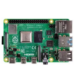

RPI4-MODBP-4GB
SBC, Raspberry Pi4 B+, BCM2711, ARM Cortex-A72, 4GB RAM, MicroSD, Wifi, 2x micro HDMI

This covert inline screen grabber sits between HDMI devices - like a computer and monitor, or console and television - to quietly capture screenshots. Perfect for sysadmins, pentesters and anyone wanting to record what's on a screen.

RF 433MHz power amplifier 500mW, 433MHz RF linear amplifier 301
PLA-05W-433AT is a linear monolithic power amplifier (classAB) suitable for amplifying 433.92MHz signals from low power RF transmitters. It offers low signal distortion and low harmonic generation. Either analog or digital input carriers between 430MHz and 435MHz are suitable. PLA-05W-433AT is ideal for applications where increased communication range is required or where RF interference causes communication problems.
RF input and output signals are via RPSMA connectors or using screw terminals, or a combination of these two types of connectors. Power supply and external amplifier allow voltages are applied through the three positions of the screw terminal.

